Fulqrum Publishing Home   |   Register   |   Today Posts   |   Members   |   UserCP   |   Calendar   |   Search   |   FAQ

Go Back   Official Fulqrum Publishing forum > Fulqrum Publishing > IL-2 Sturmovik: Cliffs of Dover > Technical threads > FM/DM threads

FM/DM threads Everything about FM/DM in CoD

Reply
 
Thread Tools Display Modes
  #1  
Old 05-16-2012, 01:42 AM
IvanK IvanK is offline
Approved Member
 
Join Date: Oct 2007
Location: Australia
Posts: 886
Default

A second related document is in the UK National Archives "AVIA 18/1281 Tests of RAE devices for the reduction of "Negative G" engine cutting on merlin engined fighter aircraft". This document details flight test data on 3 devices (Including the Schilling orifice ... though its called the RAE Restrictor .... PC in action back in the 40's).

It compares each of the devices to an unmodified aircraft. In the tables presented the G used to induce cutout are in the order of -0.5G up to -1.5G. Though emphasis of the document is on the time taken to recover from cutout rather than preventing it, despite the document title.

Given the document is not looking at specifically preventing cutout itself but rather minimising the time of the cutout it needs to be put into perspective when using it to decide on initial cutout values. However it is of interest (imo) that reasonable values of Negative G were used (i.e. significantly less than 0G) in all the tests.... i.e. not just smooth nose position changes.

In our discussion here we are only interested in unmodified systems. The jpg below is from the document referring to an unmodified or "Normal Fuel System" aeroplane
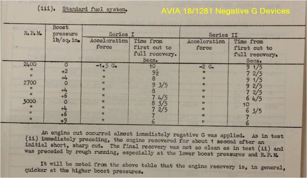

Last edited by IvanK; 05-16-2012 at 01:47 AM.
Reply With Quote
  #2  
Old 05-16-2012, 02:29 AM
Crumpp's Avatar
Crumpp Crumpp is offline
Approved Member
 
Join Date: Feb 2008
Posts: 1,552
Default

That document clearly states:

Quote:
An engine cut out occurred almost immediately negative G was applied.
Pretty clear cut but I am surprised at the amount of time it took for the Merlin to recover, 6-10 seconds and averaging ~8 seconds.

No wonder the Luftwaffe makes note of the effectiveness of bunting.
Reply With Quote
  #3  
Old 05-16-2012, 03:04 AM
WTE_Galway WTE_Galway is offline
Approved Member
 
Join Date: Jul 2008
Posts: 1,207
Default

Quote:
Originally Posted by IvanK View Post
A second related document is in the UK National Archives "AVIA 18/1281 Tests of RAE devices for the reduction of "Negative G" engine cutting on merlin engined fighter aircraft". This document details flight test data on 3 devices (Including the Schilling orifice ... though its called the RAE Restrictor .... PC in action back in the 40's).

It compares each of the devices to an unmodified aircraft. In the tables presented the G used to induce cutout are in the order of -0.5G up to -1.5G. Though emphasis of the document is on the time taken to recover from cutout rather than preventing it, despite the document title.
Its worth pointing out that the Shilling modifications (which involved more than just fitting the famous flow constrictor) main effect was to substantially delay the onset of the second stage flooding cut-off. The shilling orifice was a stopgap.

The "Shilling Orifice" did not actually fix the problem, just delayed its onset a few seconds. Sustained inverted flight was still impossible in a Shilling equipped Spitfire, that required a pressure carburetor.

Last edited by WTE_Galway; 05-16-2012 at 03:07 AM.
Reply With Quote
  #4  
Old 05-16-2012, 03:24 AM
Crumpp's Avatar
Crumpp Crumpp is offline
Approved Member
 
Join Date: Feb 2008
Posts: 1,552
Default

Quote:
which seems a tad excessive.
What you need is a G meter. That does seem kind of excessive. I got the game and can check it out.
Reply With Quote
  #5  
Old 05-16-2012, 07:11 AM
klem's Avatar
klem klem is offline
Approved Member
 
Join Date: Nov 2007
Posts: 1,653
Default

Quote:
Originally Posted by Crumpp View Post
What you need is a G meter. That does seem kind of excessive. I got the game and can check it out.
The chart I made is based on acceleration measurements taken from the game and are effectively a G-meter (accelerometer):
cur_Plane.getParameter(part.ParameterTypes.Z_Overl oad, 0); is acceleration in the fore/aft plane
cur_Plane.getParameter(part.ParameterTypes.Z_Overl oad, 1); is acceleration in the lateral plane
cur_Plane.getParameter(part.ParameterTypes.Z_Overl oad, 2); is acceleration in the vertical plane, renamed G-force on the chart.

At the moment of the 0.5G cut there were very small fore/aft and lateral g-forces of -0.04g and +0.02g respectively (slight speed reduction and slight sideslip). Its close enough to indicate that the cutout occurs well before 0.1G.

Readings were taken every 300 mSecs. Unfortunately we cannot add instruments to the cockpit so we can only draw data from the game parameters.
__________________
klem
56 Squadron RAF "Firebirds"
http://firebirds.2ndtaf.org.uk/


ASUS Sabertooth X58 /i7 950 @ 4GHz / 6Gb DDR3 1600 CAS8 / EVGA GTX570 GPU 1.28Gb superclocked / Crucial 128Gb SSD SATA III 6Gb/s, 355Mb-215Mb Read-Write / 850W PSU
Windows 7 64 bit Home Premium / Samsung 22" 226BW @ 1680 x 1050 / TrackIR4 with TrackIR5 software / Saitek X52 Pro & Rudders
Reply With Quote
  #6  
Old 05-16-2012, 06:55 PM
41Sqn_Stormcrow
Guest
 
Posts: n/a
Default

Quote:
Originally Posted by klem View Post
The chart I made is based on acceleration measurements taken from the game and are effectively a G-meter (accelerometer):
cur_Plane.getParameter(part.ParameterTypes.Z_Overl oad, 0); is acceleration in the fore/aft plane
cur_Plane.getParameter(part.ParameterTypes.Z_Overl oad, 1); is acceleration in the lateral plane
cur_Plane.getParameter(part.ParameterTypes.Z_Overl oad, 2); is acceleration in the vertical plane, renamed G-force on the chart.

At the moment of the 0.5G cut there were very small fore/aft and lateral g-forces of -0.04g and +0.02g respectively (slight speed reduction and slight sideslip). Its close enough to indicate that the cutout occurs well before 0.1G.

Readings were taken every 300 mSecs. Unfortunately we cannot add instruments to the cockpit so we can only draw data from the game parameters.
Ok that already helps a lot. But I still do not know which point the acceleration provided by cur_Plane.getParameter(part.ParameterTypes.Z_Overl oad, 2) corresponds to (I assume z-axis here is body axis not lift-axis which should have to be confirmed by devs too). Does it really correspond to the acceleration measured by the g-meter in the flight tests that stated a 0.1g threshold for the second stage cut-out? It is important to make sure that we do not compare apples with pears.
Reply With Quote
  #7  
Old 05-16-2012, 08:41 PM
klem's Avatar
klem klem is offline
Approved Member
 
Join Date: Nov 2007
Posts: 1,653
Default

Quote:
Originally Posted by 41Sqn_Stormcrow View Post
Ok that already helps a lot. But I still do not know which point the acceleration provided by cur_Plane.getParameter(part.ParameterTypes.Z_Overl oad, 2) corresponds to (I assume z-axis here is body axis not lift-axis which should have to be confirmed by devs too). Does it really correspond to the acceleration measured by the g-meter in the flight tests that stated a 0.1g threshold for the second stage cut-out? It is important to make sure that we do not compare apples with pears.
The maddox parameters do not tell us but I assume it is through the CoG. I have to assume that the parameters returned by the game are those used by 1C in development.

As far as I know there is no historical data to identify the location of the accelerometer used in the 1940 tests but it seems reasonable to suppose it would be close to the CoG to aviod variable components like moment arms during rotation. As a repeatable reference it may not have been necessary to measure the g figure at the precise location of the carburettor bowl if the reduced/negative G were induced gradually.

Of course, rapid rotation would create a larger g force at a remote moment arm-end than at the CoG but if the accelerometers in the 1940 tests and the 1C model are both at the CoG then they are a reasonable comparison.

As you say the devs know the answers to this, ours is really a side discussion with proposals wildy varying from "any g reduction" to "-1.5 or more". I just thought readers would be interested to know what the game is telling us.
__________________
klem
56 Squadron RAF "Firebirds"
http://firebirds.2ndtaf.org.uk/


ASUS Sabertooth X58 /i7 950 @ 4GHz / 6Gb DDR3 1600 CAS8 / EVGA GTX570 GPU 1.28Gb superclocked / Crucial 128Gb SSD SATA III 6Gb/s, 355Mb-215Mb Read-Write / 850W PSU
Windows 7 64 bit Home Premium / Samsung 22" 226BW @ 1680 x 1050 / TrackIR4 with TrackIR5 software / Saitek X52 Pro & Rudders
Reply With Quote
  #8  
Old 05-20-2012, 02:12 PM
41Sqn_Stormcrow
Guest
 
Posts: n/a
Default

Is there a way to show the flown z-axis g load while flying, for instance in one of the windows? Would be great to do so for flight testing.
Reply With Quote
Reply


Posting Rules
You may not post new threads
You may not post replies
You may not post attachments
You may not edit your posts

BB code is On
Smilies are On
[IMG] code is On
HTML code is Off

Forum Jump


All times are GMT. The time now is 06:05 PM.


Powered by vBulletin® Version 3.8.4
Copyright ©2000 - 2025, Jelsoft Enterprises Ltd.
Copyright © 2007 Fulqrum Publishing. All rights reserved.