Fulqrum Publishing Home   |   Register   |   Today Posts   |   Members   |   UserCP   |   Calendar   |   Search   |   FAQ

Go Back   Official Fulqrum Publishing forum > Fulqrum Publishing > IL-2 Sturmovik

IL-2 Sturmovik The famous combat flight simulator.

Reply
 
Thread Tools Display Modes
  #1  
Old 12-20-2010, 07:22 PM
JG27CaptStubing JG27CaptStubing is offline
Approved Member
 
Join Date: Dec 2007
Posts: 330
Default

Quote:
Originally Posted by Azimech View Post
I think it's the oil cooler.
Actually it's an intercooler to keep the air going back to the turbos from Frying them...Also lowering the tempurature makes the air thicker. Interesting to see how its both Turbo Charged and SuperCharged.
Reply With Quote
  #2  
Old 12-20-2010, 07:48 PM
T}{OR's Avatar
T}{OR T}{OR is offline
Approved Member
 
Join Date: Feb 2008
Location: Zagreb, Croatia
Posts: 833
Default

Quote:
Originally Posted by JG27CaptStubing View Post
Actually it's an intercooler to keep the air going back to the turbos from Frying them...Also lowering the tempurature makes the air thicker. Interesting to see how its both Turbo Charged and SuperCharged.
TC's inter-cooler is below the cockpit - that big heat exchanger. If it indeed is the second inter-cooler it could only be related with SC, to cool the air after it passes through SC. Watch how the air/exhaust flows and how the pipeline is designed.

I would still go with the oil cooler, like Azimech said.
__________________

LEVEL BOMBING MANUAL v2.0 | Dedicated Bomber Squadron
'MUSTANG' - compilation of online air victories

Last edited by T}{OR; 12-20-2010 at 07:52 PM.
Reply With Quote
  #3  
Old 12-20-2010, 07:50 PM
swiss swiss is offline
Approved Member
 
Join Date: Mar 2010
Location: Zürich, Swiss Confederation
Posts: 2,266
Default

BUT:
1.
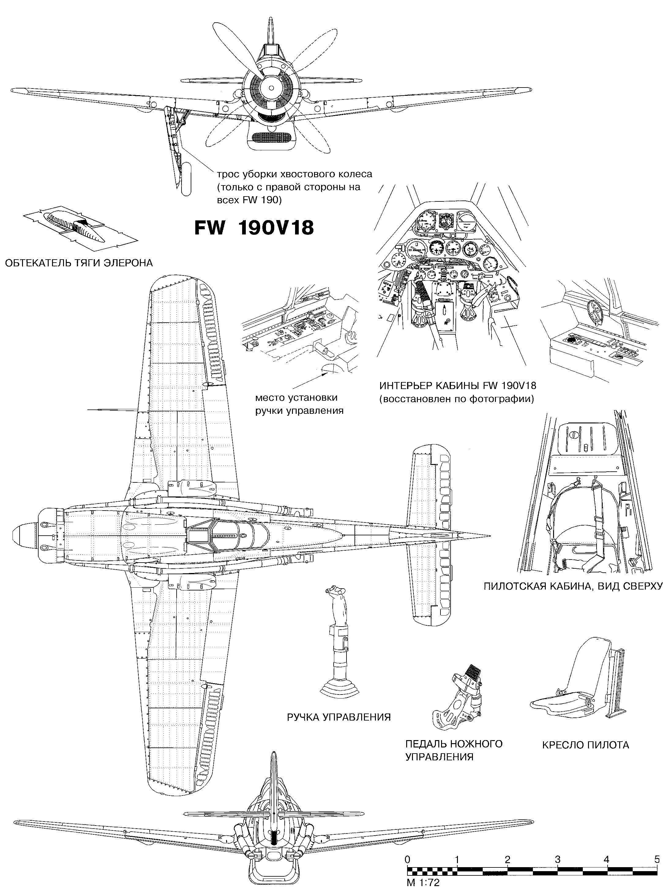
Looking at the blueprint it looks like:
SC->IC->Turbo->Intake
Which I think is odd, very odd. I would expect the highest pressure/temp rise passing the turbo.


2.
Another funny thing is the exhaust manifold and the tubing, outside the airplane.
@10K amsl you got what, -35°?
And your flying >600kph.
Now, cooling down the exhaust gases can't really add to the efficiency, or am I wrong?


Any thoughts?


EDIT:
Point one seems wrong after drawing some lines - but now the setup looks even weirder.


I mean, I would expect they bypassed the SC at some rpm level(And maybe shared the IC for it too), if my drawing are correct, it's more like Turbo->IC->SC->Intake.

Last edited by swiss; 12-22-2010 at 09:58 PM.
Reply With Quote
  #4  
Old 12-20-2010, 08:13 PM
T}{OR's Avatar
T}{OR T}{OR is offline
Approved Member
 
Join Date: Feb 2008
Location: Zagreb, Croatia
Posts: 833
Default

Quote:
Originally Posted by swiss View Post
He was talking about the thing under the engine, which an oil to air "heat exchange device".
The big one in the belly is the IC.
Your 2nd point is right, the first one wrong, the compressed air never goes "back" to the turbo.
Also, the turbo has to deal with way higher temp(exhaust gases) then the compressed air could ever reach.
Usually it's like:
Filter(if there is)->Turbo(rise in temp due compression)->IC->Intake
Now I have to correct you on this one.

Turbine is just that - a turbine. Turbocharger is driven by the kinetic energy of exhaust gases. It does not use the same exhaust gases to feed the engine. It sucks in the same air the normal, mechanically driven supercharger would.

The only scenario where you would use (recirculated) exhaust gases is when you want to lower emissions set by certain standard (e.g. EGR valve). And this is way too modern technology for WW2.

Quote:
Originally Posted by swiss View Post
BUT:
1.
Looking at the blueprint it looks like:
SC->IC->Turbo->Intake
Which I think is odd, very odd. I would expect the highest pressure/temp rise passing the turbo.


2.
Another funny thing is the exhaust manifold and the tubing, outside the airplane.
@10K amsl you got what, -35°?
And your flying >600kph.
Now, cooling down the exhaust gases can't really add to the efficiency, or am I wrong?


Any thoughts?
I too think this would be odd. This is the way I understood it (twice as shorter route / intake manifold):

Exhaust valves / TC + fresh air => IC (for TC) => SC > engine intake valves (or manifold if you want).
__________________

LEVEL BOMBING MANUAL v2.0 | Dedicated Bomber Squadron
'MUSTANG' - compilation of online air victories
Reply With Quote
  #5  
Old 12-20-2010, 08:34 PM
swiss swiss is offline
Approved Member
 
Join Date: Mar 2010
Location: Zürich, Swiss Confederation
Posts: 2,266
Default

Maybe because you misunderstood the drawing...

Red: Exhaust
light blue: fresh compressed hot air
blue: cooled down compressed air

I did not draw the point where the exhaust gases leve the system, nor the the actual intake.

Back to the 190:

Quote:
Exhaust valves / TC + fresh air => IC (for TC) => SC > engine intake valves (or manifold if you want).

Last edited by swiss; 12-22-2010 at 09:59 PM.
Reply With Quote
  #6  
Old 12-20-2010, 08:45 PM
T}{OR's Avatar
T}{OR T}{OR is offline
Approved Member
 
Join Date: Feb 2008
Location: Zagreb, Croatia
Posts: 833
Default

Quote:
Originally Posted by swiss View Post
Thanks thor, really, really, nice from you. Again, I am aware how a turbo system works.
Where, btw, did I suggest to return exhaust gases?
I honestly apologize if I offended you in any way. Please to re-read what you wrote (why I misunderstood you). Also, I just saw the drawing - which you added later on by editing the post.


Quote:
Originally Posted by swiss View Post
Maybe because you misunderstood the drawing...

Red: Exhaust
light blue: fresh compressed hot air
blue: cooled down compressed air

I did not draw the point where the exhaust gases leve the system, nor the the actual intake.
What you drew looks alright by me. Azimech also understood it like I did.
__________________

LEVEL BOMBING MANUAL v2.0 | Dedicated Bomber Squadron
'MUSTANG' - compilation of online air victories
Reply With Quote
  #7  
Old 12-20-2010, 09:33 PM
swiss swiss is offline
Approved Member
 
Join Date: Mar 2010
Location: Zürich, Swiss Confederation
Posts: 2,266
Default

Great, we finally agree.


But I still dont get Turbo->SC.
It says they used an additional turbo, but nowhere a modified charger, which they probably had to, since it had to deal with altered pressure.
Also, I thought SC work with lower pressure compared to turbos.
Plus, the SC is fed with (still)hot air and heats its up again.
I have some doubts concerning efficiency, what is the SC's purpose? Reduce IC lag?

I guess I'll have to do some research.

Quote:
looks similar to a p47 in concept,
Not really, the P47 just had a turbo/IC setup - but they called it "exhaust-supercharger" which adds to the confusion.
That is according to the infos I just found. I'd be more than happy to hear about a combo system.


Last edited by swiss; 12-20-2010 at 09:51 PM.
Reply With Quote
  #8  
Old 12-20-2010, 10:35 PM
koivis koivis is offline
Approved Member
 
Join Date: Oct 2009
Posts: 53
Default

Quote:
Originally Posted by swiss View Post
Not really, the P47 just had a turbo/IC setup - but they called it "exhaust-supercharger" which adds to the confusion.
Well, actually it was a similar system to Fw 190C. As far as I know, every P&W R-2800 made also had an internal supercharger mounted directly behind the engine, driven by the crankshaft. The confusing thing here is, that while the air from turbocharger went indeed to the carburetor, from there it continued to the supercharger! After that, it's of course going to cylinders. Some pictures to clarify:

P-47 Engine, supercharger in blue colour, carburetor is the black thing on top of it:


Another view, showing the duct leading to carb, blue object is the supercharger:


Rolls Royce Merlin had almost the same setup (I think most WW2 engines did), except it had an liquid cooled intercooler as the last thing before the intake. Also of note here (two stage version) is that the air is cooled between the stages too!


Hope this helps, I get sometimes confused with this technology too.
__________________
~~~~~~~~~~~~~~~~~~~
Redguys Air Racing Team
Member A4
www.simairracing.com

"The fastest pilots of the online world..."

Last edited by koivis; 12-20-2010 at 10:38 PM.
Reply With Quote
  #9  
Old 12-20-2010, 08:20 PM
Tempest123's Avatar
Tempest123 Tempest123 is offline
Approved Member
 
Join Date: Dec 2009
Posts: 389
Default

Interesting, looks simililar to a p47 in concept, i would guess that cooling down the exhaust just allowed lower temps in the turbo parts, maybe better for extended use? What was the range of the 190c, was it a short range interceptor?
Reply With Quote
  #10  
Old 12-20-2010, 08:23 PM
Azimech's Avatar
Azimech Azimech is offline
Approved Member
 
Join Date: Sep 2009
Location: Leerdam, The Netherlands
Posts: 428
Default

No, the supercharger on the DB60x series is fitted directly to the intake manifold.

The path is Air-Turbo-Intercooler-Supercharger-Intake-Exhaust-Turbo-Air

The amount of energy in the exhaust gasses is so tremendous that even flying with -50 C hardly cools it, and the pressure remains high until the gas has expanded behind the turbo.

Edit: Thor was sooner
Reply With Quote
Reply


Posting Rules
You may not post new threads
You may not post replies
You may not post attachments
You may not edit your posts

BB code is On
Smilies are On
[IMG] code is On
HTML code is Off

Forum Jump


All times are GMT. The time now is 08:16 AM.


Powered by vBulletin® Version 3.8.4
Copyright ©2000 - 2025, Jelsoft Enterprises Ltd.
Copyright © 2007 Fulqrum Publishing. All rights reserved.