
|
|
#51
 10-31-2011, 06:22 PM
|
||||
|
||||
|
Quote:
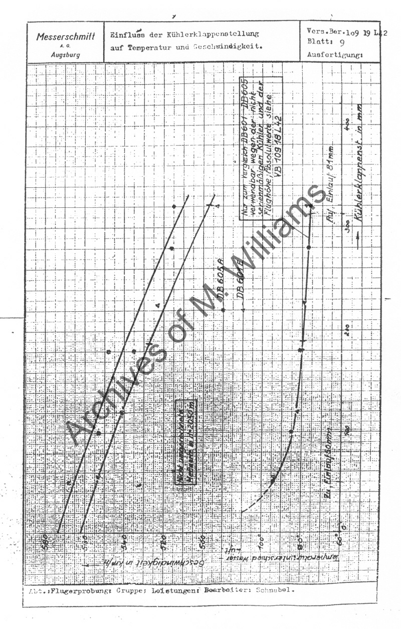 Note, speed is on the bottom (x axis), it is hard to read but it looks like it goes from (left) 520 - 530 - 540 - 550 - 560(right) If that is the case, than the diff is only ~5kph PS this is for a 109G not a 109E, correct me if I am wrong but they totally re-worked the rads on the later 109s models (F onward?) So, not sure how this applies to the E if at all other than to show the rad does affect the speed a little
__________________
Theres a reason for instrumenting a plane for test..
That being a pilots's 'perception' of what is going on can be very different from what is 'actually' going on. 
|
|
#52
10-31-2011, 06:23 PM
|
||||
|
||||
|
left=580 right=500
if you twist the whole doc 90° to the right, you can read it a lot easier! btw those two straight lines show the db601 and the db 605 engine,...the curve on the right(as you call it), which in my opinion is on the bottom of the diagram, shows the rad settings in mm.
__________________

Last edited by David198502; 10-31-2011 at 06:27 PM.
|
|
#53
10-31-2011, 06:24 PM
|
||||
|
||||
|
Quote:
What is more important to point out here is The total lack of any data you provided to support your claim!! That is the real joke here, how you condem 1C based on nothing what so ever!
__________________
Theres a reason for instrumenting a plane for test..
That being a pilots's 'perception' of what is going on can be very different from what is 'actually' going on.
|
|
#54
10-31-2011, 06:24 PM
|
||||
|
||||
|
The difference is about 50 km/h as i read it, as the two lines represent the DB601 and the DB605.
__________________
Win 7/64 Ult.; Phenom II X6 1100T; ASUS Crosshair IV; 16 GB DDR3/1600 Corsair; ASUS EAH6950/2GB; Logitech G940 & the usual suspects 
|
|
#55
10-31-2011, 06:29 PM
|
||||
|
||||
|
Quote:
__________________
|
|
#56
10-31-2011, 06:29 PM
|
||||
|
||||
|
Quote:
1st curve intersects the bottom (x axis) at ~574 2nd curve intersects the bottom (x axis) at ~563 11 = 574 - 563 So where did you 50kph come from? Quote:
__________________
Theres a reason for instrumenting a plane for test..
That being a pilots's 'perception' of what is going on can be very different from what is 'actually' going on.
|
|
#57
10-31-2011, 06:30 PM
|
|||
|
|||
|
Quote:
You hve to understand that cooling has always been a prob in aviation. The more the speed the more the drag you get with a cooling device and the less cooling effect you hve Here is an interesting article related to this : Quote from user "Brian Abraham" It would seem from the drawing that the design did not draw upon Merediths work. I'm not sure exactly how you are defining the "first with a belly scoop". To me the Hurricane would seem to fit the bill of having a belly scoop (first or not), though I don't know if it embodied Merediths drag reduction ideas as did the Spitfire and P-51. Edited to add I came across this article written by J. Leland Atwood of North American at An engineer's perspective on the Mustang | Flight Journal | Find Articles at BNET North American Aviation (NAA) Mustang fighter is generally credited with a 20- to 30mph speed advantage over most of its WW II contemporaries . This speed advantage also permitted a considerable increase in range that required more fuel, but not enough to significantly reduce speed. Records show that some 275 U.S. aces were "made" in P-51s. The reasons for the Mustang's significant performance capability have never been clearly explained, and I hope to clarify why its aerodynamic features enabled this capability. To begin: in 1940, the British Purchasing Commission, which I dealt with, had a member-H.C.B. Thomas from Farnborough whom I found to be familiar with the Meredith Report. This report outlined a feature that could enhance the performance of any internal-combustion engine at high speeds by using a radiator form of heat dissipation. A low-velocity airflow through the radiator was one element of this, and it was apparent to me that the larger the radiator, the lower the speed of the air flowing through it; this approached one of the Meredith Report's objectives. I therefore offered Mr. Thomas sketches and other descriptions of a Mustang design that had the main radiator in the rear of the fuselage. The alternatives were wing radiators such as those used on the Spitfire and the Bf 109, and under-engine radiators such the P-40's; both positions limited radiator size and the length and size of the ducting that could be used to handle and control the cooling air. In addition to the radiator's rearward position, after the design contract had been awarded and at the recommendation of NAA's aerodynamics group, it was decided to use a new airfoil of a class generally designated as "laminar flow." This was being developed at NACA (later NASA) at Langley Field, Virginia. A 1939 report by Eastman Jacobs and others at Langley contained the results of the tests of some small laminar-flow airfoils. The drag on these small models was quite low, and there was some hope that laminar flow could be achieved much farther back on an airfoil than had been predicted by previous investigators. The publishers of the report, however, warned that they had not been able to obtain laminar flow on wings of anywhere near the size of those required for actual aircraft and that their tests were to be taken only as the results from laminar-flow models of not more than six inches in width. In spite of this warning, however, both Ed Horkey (leading aerodynamicist at North American) and Bell Aircraft's chief engineer, Robert Woods, decided to try laminar-flow profiles on the P-51 and the Bell P-63, respectively. These airfoils were incorporated on the Mustang and the Bell airplane with the hope that laminar flow could be extended well back on their wings. Extensive efforts were made to polish and protect the P-63 wing's leading edge profile, but the results were equivocal. Those who advocated the laminar flow wing felt that the Mustang's outstanding performance resulted from laminar flow over most of the wing. Kingcobra designers felt they were getting a similar effect, although that aircraft's performance did not justify this conclusion. With respect to the Mustang, many tests-including some in recent years-have shown that extensive laminar flow was not developed on the Mustang wing and that the drag of the wing was probably no less than that of conventional wings of the same thickness and taper ratio. On the other hand, the Mustang's cooling drag was much lower. This was the result of using a ducted radiator with a large area and a slow-speed airflow through it (Pr and P2); closing up the exit and creating a back pressure restored the momentum of the cooling of air (momentum lost in radiator transit). This was possible because of the radiator's cooling capability, which, to be adequate in a full-power climb, was much more than that required at high speed and high dynamic pressure. According to calculations given in a supporting paper, the drag created by momentum loss in passing through the radiator can be reduced from some 400 pounds to close to 30 to 40 pounds because of the offsetting momentum of the jet thrust from the radiator exit (V2). Since these two effects, i.e., the wing drag and the radiator momentum recovery, have never been disentangled in the literature, a technical reason for the Mustang's performance has never been clearly identified. NACA had taken the lead in airfoil development and had worked out a large series of airfoils that were used generally throughout the industry. For instance, the Spitfire wing was of the NACA 2200 series-13 percent thick at the root and 6 percent thick at the tip. This is the same airfoil series as is used on the DC-2 and the original North American BT-9 and AT-6 trainers. To improve the stall characteristics, I later changed the NACA 2200 series on the AT-6 trainer to the 4412 at the tip. It is quite probable that the Spitfire's wing, being only 6 percent thick at the tip, had a lower drag than the Mustang's wing as actually incorporated. The point of all this is that nearly all WW II fighters operated at Mach numbers of .65 or less. The primary advantage presented by the so-called laminar-flow wing was therefore not in drag reduction but in high-speed dives, where temporary airspeed shock waves were created on the wing's upper surfaces and a loss of control and lift occurred as the critical Mach number was exceeded. This was a phenomenon we called "compressibility," and it became the subject of a huge amount of research. The Mustang pilot, with his laminarflow wing, had a higher critical Mach number, so he could point the nose down and know he could out-dive virtually any airplane and recover relatively easily. The P47 and P-38, however, with their older, fatter wings would hit compressibility and have to use their dive flaps to recover safely. So, besides being an overall clean design, the legendary Mustang's speed and range rest as much on carefully designed radiator airflow as on anything else. As is often the case in aircraft design, it was the seemingly small details that counted. It's not completely true in every line but it's in concordance with what we have to know. (extracted from here : http://www.pprune.org/aviation-histo...first-one.html) Pls note that the 109 had far more cooling power than the Spit wld get in all models. If you look at the 110 rads, you'll understand that the 109 was made for sustaining max power far more longer than any other warplane at the time in Eu. There is no secret, it's only tweaking Last edited by TomcatViP; 10-31-2011 at 06:36 PM.
|
|
#58
10-31-2011, 06:31 PM
|
||||
|
||||
|
Quote:
But I am not suprised, in that your not the first to come here with nothing and make a baseless claim.
__________________
Theres a reason for instrumenting a plane for test..
That being a pilots's 'perception' of what is going on can be very different from what is 'actually' going on.
|
|
#59
10-31-2011, 06:31 PM
|
||||
|
||||
|
Quote:
well proven or not, your doc states a difference of 50kph, which is not the case in the game...
__________________
|
|
#60
10-31-2011, 06:35 PM
|
||||
|
||||
|
Quote:
__________________
|
 |
|
|


 Linear Mode

