
|
|
|||||||
| IL-2 Sturmovik The famous combat flight simulator. |
 |
|
|
Thread Tools | Display Modes |
|
|
|
#1
 11-27-2009, 10:10 PM
|
||||
|
||||
|
Possibly the "pin" is actually a spring loaded ball detent, which would act like a friction to hold the selected position
__________________
 GigaByteBoard...64bit...FX 4300 3.8, G. Skill sniper 1866 32GB, EVGA GTX 660 ti 3gb, Raptor 64mb cache, Planar 120Hz 2ms, CH controls, Tir5 
|
|
#2
11-27-2009, 10:43 PM
|
|||
|
|||
|
Quote:
Ahhh! Now that makes sense. That would suggest that planes with this system would, in effect, have a limited number of prop pitch settings (as many as holes on the disk).
|
|
#3
11-28-2009, 12:13 PM
|
|||
|
|||
|
If it's a governor for a constant speed unit you don't directly set the prop pitch through any setting. What your actually setting is the RPM. The CSU sets the prop pitch to what ever it needs to maintain the RPM at a given throttle setting if it can (any where between coarse and fine).
It's hard to see but if you look at the cut away diagram on the link, the disk is attached to the "speed control shaft" (No 1 on the diagram, but then again my eyes are dim and weak with old age) Last edited by Skoshi Tiger; 11-28-2009 at 12:17 PM.
|
|
#4
11-28-2009, 01:23 PM
|
||||
|
||||
|
(quote)
That would suggest that planes with this system would, in effect, have a limited number of prop pitch settings (as many as holes on the disk). It appear's that the setting was in increment value of five (5)
__________________
GigaByteBoard...64bit...FX 4300 3.8, G. Skill sniper 1866 32GB, EVGA GTX 660 ti 3gb, Raptor 64mb cache, Planar 120Hz 2ms, CH controls, Tir5
|
|
#5
11-28-2009, 05:38 PM
|
|||
|
|||
|
The holes are more likely to be for attaching and adjusting the linkage, the fact that there's so many of them is to adjust movement set by the throttle.
The position of this set the props rpm limit and the governor controls the overspeed/underspeed condition of the propeller. The holes are not related to the pitch angles "The propeller governor maintains a constant engine speed by controlling propeller pitch. Engine speed is selected by a cockpit control connected to the governor speed control shaft." EDit Shoshi Tiger had explained it well enough. Last edited by KG26_Alpha; 11-28-2009 at 05:53 PM.
|
|
#6
11-28-2009, 09:46 PM
|
||||
|
||||
|
It's not likely that the holes are for a linkage point because of the interference of the so called "pin' area (its clearly butted against the disk), there would be no clearence for the linkage mechanical attachment if the disk is designed to rotate 360 degrees. We are all just guessing here, but I think a ball detent is the most likely explanation.
__________________
GigaByteBoard...64bit...FX 4300 3.8, G. Skill sniper 1866 32GB, EVGA GTX 660 ti 3gb, Raptor 64mb cache, Planar 120Hz 2ms, CH controls, Tir5
|
|
#7
11-28-2009, 09:56 PM
|
|||
|
|||
|
Quote:
this is what I mean by the holes are used for installing linkages 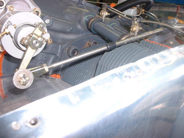
|
|
|
|


 Hybrid Mode
