
|
|
#141
 05-14-2012, 05:40 AM
|
|||
|
|||
|
Quote:
Quote:
The wings obviously did not fall off the 190 in that test. So, I guess we can assume that at that dive angle, starting altitude, starting speed...etc, that the 190 stayed within the dive limits. Probably a vertical dive angle is a different story and the wings fall off. 
|
|
#142
05-14-2012, 06:28 AM
|
|||
|
|||
|
What's name for P47 isn't important, you may call it "old woman", but p47's acceleration is still one of the best.
In 1943 July, p47 was equipped with old naca-16 propeller whose efficiency is low at low TAS, but when P47 had a paddle prop., story changed. I guess fw190G can only slightly outdive P47 (paddle) at the beginning. Last edited by BlackBerry; 05-14-2012 at 06:33 AM.
|
|
#143
05-14-2012, 09:07 PM
|
||||
|
||||
|
Hi Blackberry,
You have drawn some of the right conclusions but there is some work required still. First of all, these are constant speed propellers. They change pitch as required. I am sure you got confused looking at that single F4U graph but it is a fact, you cannot compare CSP propellers at different advance ratios. The advance ratio does not tell you a thing except in the context of that specific pitch angle. Now what you are doing is how that pitch stops are determined. A good propeller design will keep the polar at the flat area on the top as the pitch of the blade changes throughout the flight envelope. This is what a complete CSP efficiency over advance ratio graph looks like:  The best aircraft/engine for this propeller will achieve Vmax at ~2.2 advance ratio and the propeller will have the stops at 15 degrees and 45 degrees. That is the advantage of a CSP, you maintain peak efficiency over a wide range of velocities. The F4U graph looks like it comparing airfoil selection at a specific velocity. Last edited by Crumpp; 05-14-2012 at 09:09 PM.
|
|
#144
05-15-2012, 03:45 AM
|
|||
|
|||
|
I think he knows that. The example is a bit rigged. Same max rpms, similar reduction ratios. The main difference being the diameter. He started it out by calculating max tip speed as peak efficiency. So, have to look at his advance ratio calcs on a relative performance basis verses comparing one prop to the other.
Last edited by MadBlaster; 05-15-2012 at 12:49 PM.
|
|
#145
05-15-2012, 06:26 AM
|
|||
|
|||
|
Quote:
advance ratio=J= V/(n*D) V=177 m/s, D=4.1m(13.5ft), when J varies from 1.0 to 2.5, the propeller's rpm is from 2590 to 1036 respectively, and engine rpm is between 5180 and 2072rpm(reduction ratio=0.5:1). But 5158rpm is far more than engine's max. rpm, Thus the working range of 3-blade 4.1m diameter CSP is the "red curve", other part of curve is just the calculated result. Larger prop. will always benifit from lower advance ratio when other things being equal. 12.JPG 3-blade CSP diagram a.JPG 4-blade CSP diagram b.JPG It seems that 4-blade CSP with larger diameter prop, is FAR MORE efficient than 3-blade with smaller size, especially when advance ratio is very high(diving). Assume 3-blade diagram is Fw190A8, 2700rpm engine , reduction 0.54:1, 1458rpm for 3.3m Propeller Assume 4-blade diagram is P47D, 2700rpm engine , reduction 0.5:1 or 0.56:1, 1350rpm or 1518rpm for 4.0m Propeller When both Fw190A8 and P47D dive to 6000m altitude @ 950km/h TAS=264m/s TAS=680km/h IAS=421m.p.h IAS. This speed is within Tempest MKV's permitted dive limit. Propeller efficiency for P47D:82%-85% , advance ratio=3 or 2.6 Propeller efficiency for Fw190A8:0%. advance ratio=3.3 The most important is whether il2 4.11m models detailed prop. efficiency curve? Is there Mach number in il2's FM code? Crumpp Do you know? Last edited by BlackBerry; 05-15-2012 at 10:34 AM.
|
|
#146
05-15-2012, 01:32 PM
|
|||
|
|||
|
To demostrate how important of 4-blade design compared to 3-blade, we can calculate Tempest MKV.
engine rpm 3700 or 3850, reduction ratio=0.274, prop. rpm=1013rpm or 1055 rpm ;propeller diameter=14ft=4.24m When dive to 6000m altitude @ 950km/h TAS=264m/s TAS=680km/h IAS=421m.p.h IAS. This speed is within Tempest MKV's permitted dive limit. advance ratio=J=V/(d*n)=264/(4.24*1012/60)=3.7 even bigger than Fw190A8! If Tempest was equipped with 3-blade prop, it will be badly outdived by Fw190A8, but Tempest slightly outdive P47 and P51! The reason is 4-blade prop. which provides efficiency 78%@950km/h TAS. During the war many types of fighter aircraft were produced out of the designers bag, some never even reached the prototype stage, others failed to reach Service requirements, but not a few made the grade and are now house hold words the world over. The best known in this country are, of course, the Hurricane and Spitfire, the Typhoon, Mustang and Thunderbolt, and latterly the Tempest and Meteor. Each came out in many guises and fulfilled many roles, some of which they were never designed for, but all did a grand job of work, and were at one time or another indispensable to the work of the R.A.F. Fighter Command. The Aeroplane June 21st 1946. 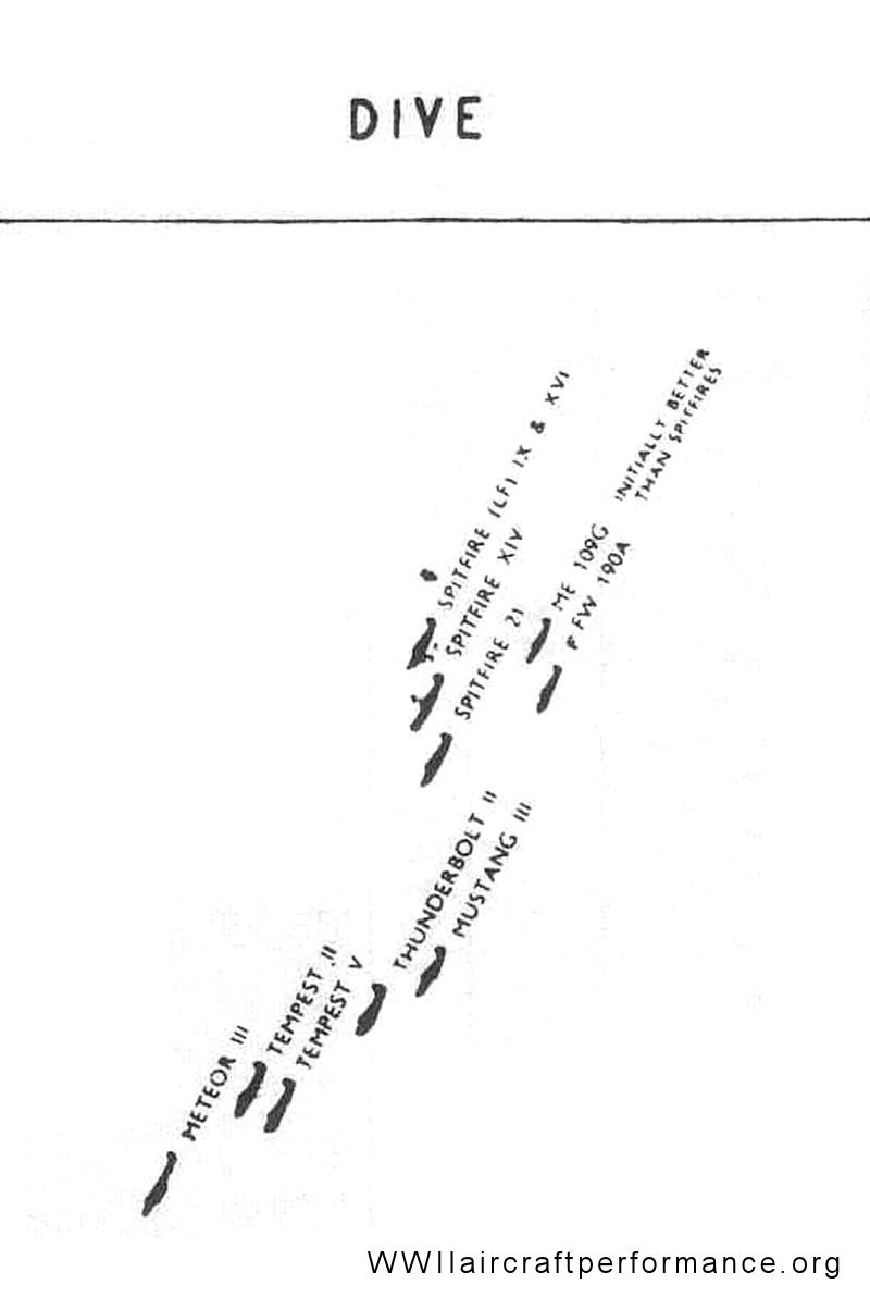 1)The best diver, Meteor, of course, not" handicapped by airscrew drag" 2)Tempest MKV(9lbs boost), the best piston diver, 4-blade prop. 5 tons, streamlined 3)Thunderbolt(P47D), the best American piston diver, 4-blade prop, 7 tons. 4) Mustang(P51B/C 18lbs boost), one of the best diver, 4-blade prop, 3.5 ton , very low drag coefficiency of laminar flow wing. 5) Fw190A8A6? Bf109G6as Spitfire IX,XIV, these a/c are outdived by P47P51Tempy. Why? Fw190A,as heavy as P51, but not laminar flow wing, lighter than P47/Tempy. only 3-blade prop. low prop efficiency at high speed. Bf109G6as, very good at initial dive stage, but not very heavy, 3-blade prop. Spitfire IX, XIV, 4-blade prop. not heavy, initially outdived by 109, but can catch up with 109 due to 4-blade efficienvy at high speed, over take 109? not sure. Last edited by BlackBerry; 05-15-2012 at 01:55 PM.
|
|
#147
05-15-2012, 03:51 PM
|
|||
|
|||
|
3-blade and 4-blade diagrams are from university textbook of aerodynamics.
I don't know those props are modern or WWII era. So they are just for demonstrate, but apperently, xfu4-1 13.5ft naca16 or clark y propeller is much inferior to that 3-blade diagram. For example, 400mph @6000m xf4u's efficiency is 70%, advance ratio=2, while in that 3-blade diagrams, could reach 85%+. So this implies that fw190a8 will completely lose its power much below 950km/h@6000m. Sad news for germans, because bf109/fw190 including Ta152 are equipped with 3-blade prop. while allied had 4-blade after 1942. Even worse for soviet planes, la5/la7,yak are light, small size plane which means their dive acceleration are poor within 730km/h. BWT, prop. efficiency decreases when altitude grows, and I don't know whether those diagrams are sea level or 9000 m. I am afraid that the efficiency diagrams of WWII era are difficult to find. The last choice is "ansys" which is powerful software in simulating propeller. Last edited by BlackBerry; 05-15-2012 at 04:42 PM.
|
|
#148
05-15-2012, 04:49 PM
|
||||
|
||||
|
Quote:
Good design can achieve the same efficiency and thrust with either 3 blades or 4 blades at the power levels of WWII aircraft. As for propeller efficiency, there is a good reason why n=.85 is a good assumption to make for CSP propeller efficiency. Take the top of your single pitch effiiciency curve for the F4U and that is the efficiency a CSP will maintain throughout the envelope. It will adjust the blade angle to maintain that. Examine n under various conditions and advance ratios in this article. This is a good primer for propeller performance btw. You will see that n has a very small variance and even remains the same at different advance ratio because of the shape of the curve at that blade angle. http://www.nar-associates.com/techni...ncy_screen.pdf More blades = more drag but those airplanes have more thrust than the blades add drag because of their weight. Align those aircraft by weight and you will see the important of it to achieving a high Vne. That being said, mach limits and dynamic pressure limits have a much more practical impact on determining Vne. Quote:
The excess propeller thrust is why the Bf-109 and FW-190 have such high initial dive acelerations under the conditions the article is talking about. If you dove all of those aircraft from Vmax, they would have no excess propeller thrust and would be using a component of weight as thrust. Quote:
The radial of the FW190 will consume more gas and oil so its weight will change faster but the P51 has more gas and potential to change weight at a slower rate. The P51 also has a lower Drag picture so does not require as much thrust to achieve a higher speed. That is why it is faster than the FW-190A8 with a less powerful engine. Laminar flow has what is termed the "drag bucket" in the middle of the polar that occurs around cruise co-efficients of lift. It has no bearing on either low speed or Vmax performance except that laminar flow airfoils as a general characteristic exhibit lower CLmax. For your games purposes, that is irrelevant as you do not have to guess CLmax but can easily calculate it from stall speed with a given weight. The Mustang achieves a higher Vmax in level flight so it was also achieve a higher Vmax in a dive provided it does not reach mach limitations or dynamic pressure limitations. You can see from this sustained turn performance analysis the general effects of thrust and aerodynamic limitations of these designs. 
Last edited by Crumpp; 05-15-2012 at 08:27 PM.
|
|
#149
05-15-2012, 05:06 PM
|
||||
|
||||
|
Summary of propeller design:
Fewer blades = more efficiency Fewer blades = lower power loading More blades = better power loading More blades = less efficiency Larger disc size = better power loading Larger disc size = faster tip speeds = lower efficiency = good for low speed work Smaller disc = slower tip speeds = higher efficiency = good for high speed work Propellers are undoubtedly the most complicated piece of engineering on an aircraft. You can also bet that all the engineers during WWII did their homework. I know Mtt and Focke Wulf both tested 4 bladed designs on their aircraft. It was found that what one design made up in efficiency, it lost in power loading and vice versa. As such Focke Wulf concluded that was no appreciable difference other than weight savings on the 3 bladed propeller. The German propeller designer took the approach of widening the blade chord to increase power loading and using a better material. The allies added more blades and accepted the weight increase. Both are perfectly acceptable approaches to increasing performance with very little to choose from. The most efficient propeller would have one very long and wide blade. It would revolve rather slowly and acelerate rather poorly. All the best, Crumpp
|
|
#150
05-16-2012, 05:10 AM
|
|||||
|
|||||
|
Quote:
http://history.nasa.gov/SP-4219/Chapter3.html  Graph and sketch hand-drawn by John Stack, 1933. The effect of compressibility on the power required for a hypothetical airplane.This sketch was subsequently sent to the October 1933 Committee Meeting of the NACA in Washington. From the John Stack papers at the NASA Langley Archives. Quote:
Yes, all the engineers during WWII did their homework. However, why allied engineers accepted the weight(drag) increased by the 4th blade, and why german engineers denied? allied side: Quote:
Quote:
Allied said laminar airfoil actually reduced drag in P51, but german believed it's an impossible goal when Reynold Numbers is high(real flight ). Who made the mistakes? This unclassified file<<where we stand>> at Page 45 says: http://www.governmentattic.org/vonK/...VKarman_V2.pdf Quote:
Hamilton Standard :NACA-16 laminar flow airfoil,4-blade prop. widely used in P47P51 etc. UK de Havilland Propellers was established in 1935, as a division of the de Havilland Aircraft company when that company acquired a license from the Hamilton Standard company of America for the manufacture of variable pitch propellers. The division was incorporated as a separate company on 27 April 1947. SpitfireIX,XIV, Tempest also have laminar flow airfoil,4-blade prop. As XF4U-1 diagram indicated, 3-blade NACA16(laminar) and 3-blade Clark-Y propeller are roughly the same efficiency(within 3%), after 1942 alomost all allied laminar prop had 4 blade, later Spitfire even had 5-blade prop. There must be enough reason for allied engineers to prefer 4-blade. If allied found that was no appreciable difference other than weight savings on the 3 bladed propeller, they would drop 4-blade design just like Germans did. Those two diagrams from university textbook maybe demonstrate the difference between 3-blade laminar and 4-blade laminar propellers. We need exam it in future, Perhaps the diving difference mystery is just within propeller's efficiency diagrams. If il2 FM couldn't model detailed compressibility of wing and propeller between 0.8-1.0 mach, it will never be perfect in simulating WWII late a/c. Last edited by BlackBerry; 05-16-2012 at 07:56 AM.
|
 |
| Thread Tools | |
| Display Modes | |
|
|


 Linear Mode

