
|
|
|||||||
| FM/DM threads Everything about FM/DM in CoD |
 |
|
|
Thread Tools | Display Modes |
|
#12
 01-13-2012, 04:52 AM
|
|||
|
|||
|
Thank you very much Banks and everyone, I think this now gives the full picture! The document you have posted is the full explanation of how the system worked pre 100 octane conversion (rated boost=6.25psi, override boost is maximum possible).
From AP1590B posted by Lane and Banks: 261. Operation of the cut-off valve (14) substitutes suction for boost pressure in the aneroid chamber (2). This has the effect of rendering the control virtually inoperative, as the relay piston is held in the forward position, enabling the throttle to be fully opened by the hand lever at any altitude. So-pre 100 octane drilled hole, when the red tab was pulled the boost regulator piston was held in the left stop so that no control occured and the pilot could pull maximum boost (e.g. approx 20psi at ground level), as stated in previous references. The 0.093 hole was drilled through the boost cutout valve (presumably with the valve removed, otherwise you drill into the boost regulator face behind it!) I think the precise location of the hole is to avoid tapping into the supercharger inlet channel 12 (on Figure 45 in diagram posted above). Otherwise there would be strange effects on the boost operation when the cutoff valve was deactivated. The drilled boost cutout hole (with the boost cutout activated) is basically a leak from the outside air to passages connected to the supercharger inlet. Although it is no longer a closed system, the drilled hole should be under suction and hence no fuel-air should be vented. In theory the motor is running leaner when on +12psi boost via the cutout (due to outside air leaking into the supercharger intake), this tiny backflow for control purposes compared to the total flow going through the engine would probably make no difference whatoever. The lack of fuel-air venting would be good news for any Spitfire pilots that had an incendiary bullet graze their cowling I believe! Variable versus fixed datum Another thing that I found really interesting was the variable datum control, because this seemed to allow the pilot to have a separate control for boost setpoint. However this system does not seem to have actually been used in any real Spitfires. Instead, the engineers attached the lever on the variable aneroid to the throttle system so in effect, the pilot's throttle lever was no longer a direct throttle plate control but an altitude independant boost selector that did not allow you to go above a maximum. Very elegant! The initial single datum system must have been a bit odd for pilots, for instance at full throttle input on the ground (and the controller piston quietly disallowing actual full throttle to maintain 6.25psi boost), if you suddenly closed the pilot throttle input, nothing would happen initially! You would have to wait until the piston (really controlling the throttle) to move back. The boost control piston/throttle level/throttle plate linkage According to AP1590B, the linkage is not a linkage (as shown in my original post) but a differential gear instead! The mechanical logic seems to be the same though. Cheers, camber Last edited by camber; 01-13-2012 at 04:53 AM. Reason: typo 
|
|
#14
01-13-2012, 09:37 AM
|
|||
|
|||
|
Anyone got stuff for the Daimler Benz?
|
|
#15
01-13-2012, 10:56 AM
|
|||
|
|||
|
Quote:
Dont know if u can use this
|
|
#16
01-14-2012, 07:20 PM
|
|||
|
|||
|
Good posts camber!
I'm glad to be of some help. Here's a couple more figures that shed further light on the subject. From: Air Publication 1565 A, The Spitfire I Aeroplane, 1st Edition June 1938, reprinted April 1940. 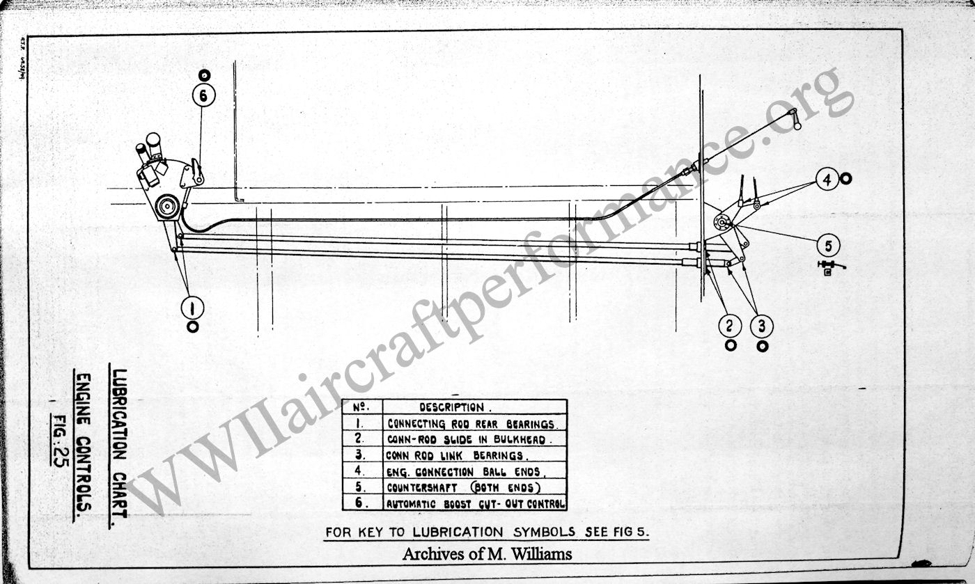 From: Air Publication 1565 A, Pilot's Notes: Spitfire I Aeroplane, May 1940 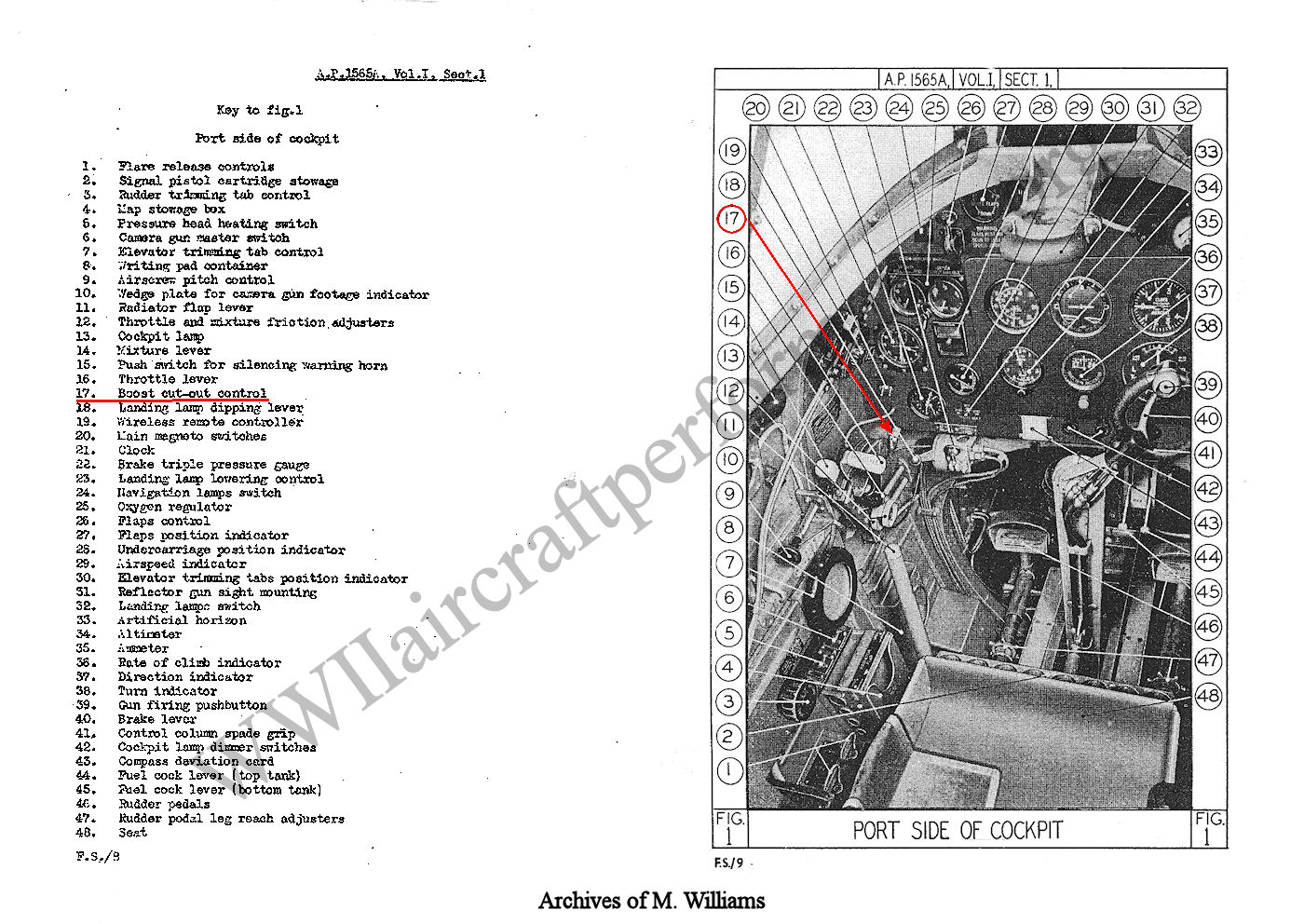
|
|
#17
01-16-2012, 10:19 AM
|
|||
|
|||
|
Thanks for the excellent research guys, very interesting stuff indeed - especially the cutaway drawing showing the internal working of the boost control unit.
It has got me confused though as my Spit II manual seems to suggest that +7 was the maximum permitted boost for use with 87 octane fuel and that this was achievable without resorting to the boost cutout switch. It only refers to using the boost cutout switch with respect to achieving the +12 combat boost value (restricted to 100 octane fuel).
|
|
#18
01-16-2012, 11:30 AM
|
|||
|
|||
|
The Merlin XII used in the Spitfire II has higher engine limits because of certain changes (e.g. it uses a different coolant, 70/30% water/glycol instead of 100% glycol). For example climb boost is +9 instead of +6 1/4.
|
|
#19
01-16-2012, 11:48 AM
|
|||
|
|||
|
Lane, that is a nice diagram showing the cable connection from red tab to the boost cutout override (no wonder it is invisible in flight sim cockpits considering where it sits!) The mechanical connections go to the control bar on the other side of the firewall that connects to the differential gear (and then on to the real carby throttle) but this is not shown.
Sutts, I would think that on the Merlin XII in Spit II rated for 100 octane, the highest boost allowed by the boost regulator setup (boost cut off red tab = OFF) would be +9psi. But with the variable aneroid in the boost controller (an improvement available by the Merlin III), the pilot can advance throttle to any boost under +9psi and the system will maintain it there as you climb. So if you have filled up with 87 fuel after landing at a station without 100 octane, you must be careful only to pull 7psi on the hand throttle. Otherwise the engine will probably let you know! If you push the red tab (boost cut off = ON) you have access to +12psi (provided altitude is low enough that the supercharger can actually achieve it). With 87 fuel this would also be a very bad idea but nothing would stop you from doing it (except a desire to keep being a fighter pilot). The thing that still confuses me is that the Spit II also has a throttle gate that allows "take off boost" of +12.5psi that is only supposed to be for taking off from small fields or overloaded. I'm not sure why both systems (boost cut-off red tab, throttle gate) need to be there at the same time.
|
|
#20
01-16-2012, 12:39 PM
|
|||
|
|||
|
IIRC Pilot's Notes General (1st Edition) mentions that the special take-off throttle position adjust the mixture to a certain rich value. I will look that up.
|
|
|
|


 Linear Mode

